
Model description
Example: M H C 160 8
M stands for module
H refers to fast thyristor and rectifier. It can also be replaced by Z and K
C: here is the position for the type of circuit. C refers to cascade, K means working with one anode and A means working with one cathode.
160: Rated current (IR(AV), IF(AV), IO)
8: Rated voltage level (*100=VDRM or VRRM)
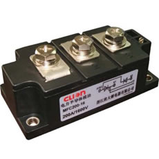
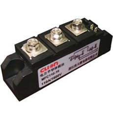
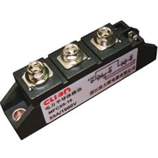
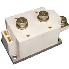
Features
1. This thyristor and rectifier module is designed with a chip which is electrical insulation to the bottom plate and operates with 2500V AC current.
2. Capsulated with international standard.
3. Fully pressure-contact structure is adopted in this thyristor and rectifier module, which is featured by good characteristics of temperature and circulating ability of power.
4. Module with current below 200A is forced to use air cooling. But with current more than 300A, water cooling or air cooling is selectable.
5. The thyristor and rectifier module is designed with light weight and small volume.
6. Easy in installation and convenient in use and maintenance.
Applications
This thyristor and rectifier module is typically used in the control and drive of motor and UPS power. Additionally, it is also used in chopper, welding equipment, inverter, heating by conduction and various forced current converter.
Instructions
1. VDRM/VRRM+200V VDSM/=VRSM
2. IGT, VGT, IH, VTM, VISO are the test value under 25℃, unless otherwise stated.
3. Other parameters in the form are test values under TJM. I2t=I2SMtw/2,tw
Technical parameters of fast thyristor module
| Mean on-state current IT(AV) | Shell tem- pera- ture TC |
Repet- itive off-state reverse voltage VDRM/ VRRM |
Peak on-state voltage /current VTM/ITM |
Repeti- tive off-state forward/ reverse current IDRM /IRRM |
Trigger current IGT | Trigger voltage VGT | Holding current IH | Critical rate of rise of off-state voltage Dv/dt |
Critical rate of rise of on-state current Di/dt |
Turn-off time tq | The-rmal resis- tance Rjc |
High- est rated junc- tion tem- pera- ture Tjm |
Isola- tion vol- tage Viso |
Out- line |
|
| A | ℃ | V | V | A | mA | mA | V | mA | V/μs | A/μs | US | ℃/W | ℃ | V(AC) | |
| 55 | 85 | 600-1600 | 1.78 | 165 | 30 | 150 | 2.5 | 60 | 800 | 200 | 15-30 | 0.120 | 125 | 2500 | MQ09 |
| 90 | 85 | 600-1600 | 1.78 | 270 | 30 | 150 | 2.5 | 80 | 800 | 200 | 15-30 | 0.180 | 125 | 2500 | MQ10 |
| 160 | 85 | 600-1600 | 1.78 | 480 | 40 | 180 | 2.5 | 100 | 800 | 200 | 15-35 | 0.140 | 125 | 2500 | MQ11 |
| 200 | 85 | 600-1600 | 1.77 | 600 | 50 | 180 | 2.5 | 100 | 800 | 200 | 15-35 | 0.100 | 125 | 2500 | MQ12 |
| 300 | 85 | 600-1600 | 1.75 | 900 | 80 | 200 | 3.0 | 100 | 800 | 200 | 15-35 | 0.070 | 125 | 2500 | MQ12 |
| 500 | 55 | 600-1600 | 2.20 | 1500 | 80 | 200 | 3.0 | 100 | 800 | 200 | 15-35 | 0.110 | 125 | 2500 | MQ14 |
| 500 | 55 | 600-1600 | 2.10 | 1500 | 80 | 200 | 3.0 | 100 | 800 | 200 | 15-35 | 0.087 | 125 | 2500 | MQ17 |
| Mean forward current IT(AV) | Shell temperature TC | Repetitive off-state reverse voltage VDRM/VRRM | Mean forward voltage /current VFM/IFM | Repetitive peak reverse current IRRM | RMS forward current IF(RMS) | Non-repeat forward surge current of one cycle IFSM | Reverse recovery time trr | Highest rated junction temperature Tjm | Isolation voltage Viso | Outline | |
| A | ℃ | V | V | A | mA | mA | A ×1000 | μs | ℃ | V(AC) | |
| 55 | 85 | 600-1600 | 1.60 | 165 | 20 | 85 | 1.6 | 2 | 140 | 2500 | MQ09 |
| 90 | 85 | 600-1600 | 1. 60 | 270 | 20 | 135 | 2.6 | 2 | 140 | 2500 | MQ10 |
| 160 | 85 | 600-1600 | 1.60 | 450 | 30 | 236 | 4.30 | 2 | 140 | 2500 | MQ11 |
| 200 | 85 | 600-1600 | 1.58 | 600 | 40 | 314 | 6.00 | 2 | 140 | 2500 | MQ12 |
| 300 | 85 | 600-1600 | 1.58 | 900 | 70 | 471 | 8.30 | 3 | 140 | 2500 | MQ12 |
| 500 | 55 | 600-1600 | 2.05 | 1500 | 70 | 471 | 6.00 | 3 | 140 | 2500 | MQ14 |
| 500* | 55 | 600-1600 | 1.90 | 1500 | 70 | 628 | 8.30 | 3 | 140 | 2500 | MQ17 |
Note:
1. * stands for cool module.
2. Type MH refers to one of MHC, MHK and MHA.
3. The parameters are the rated value and characteristics parameters of each thyristor in the module.
Electrical schematic diagram


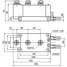
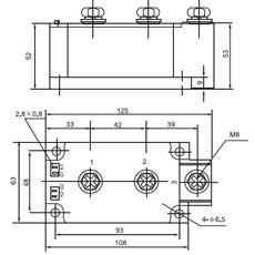
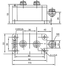
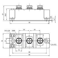
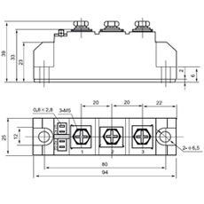
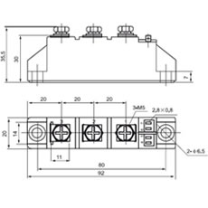
External dimensions
 Related products